Lighting Blog
Standard Operating Procedures for Professional Stage Moving Head Light Installation

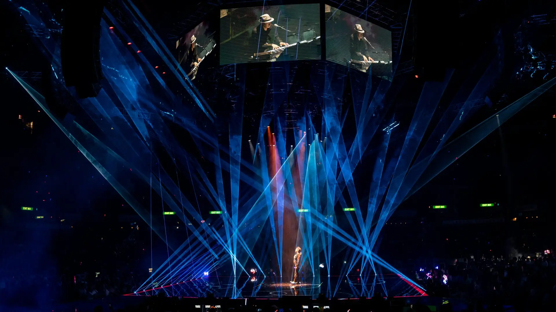
Professional stage moving head lights generally support ground placement or overhead suspension in any orientation. Overhead installations in particular must strictly follow the standard installation operating procedures for professional stage moving head lights to mitigate safety hazards such as falling equipment[1].
Improper rigging or mechanical lock clearance often triggers Pan/Tilt reset failures, detailed troubleshooting methods can be found in Moving Head Fault Troubleshooting[4].
1. Specifications for Ground Placement Installation of Stage Moving Head Lights
While ground placement appears straightforward, moving head lights generate powerful inertial torque during rapid movement. The following requirements must be fulfilled:
Level and Load-Bearing Base
The placement surface must be level, solid and vibration-free. If positioned on a wooden stage, verify its single-point load capacity well in advance. For small-scale mobile DJ scenarios, lightweight models like the 60W LED beam fixture introduced in Mini LED Beam Moving Head Datasheet[7] feature lower ground load requirements.
Anti-Slip and Securing Requirements
Do not remove the rubber shock-absorbing feet on the base under any circumstances. For setups on smooth marble or glass stage surfaces, high-friction anti-slip mats must be laid underneath the fixture base.
Lock Release Protocol
Prior to powering on the fixture, manually disengage the mechanical transit locks for Pan (horizontal rotation) and Tilt (vertical tilt). Unreleased transit locks will lead to sensor feedback errors after startup, a common fault covered in Moving Head Fault Troubleshooting[4].
2. Standard Six-Step Suspension Installation Procedure for Professional Stage Moving Head Lights
Overhead suspension carries the highest risk among all lighting rigging tasks and must be completed by strictly adhering to the six-step workflow below[2]. Large EDM festival rigs with dozens of suspended beam lights impose stricter load control standards, as explained in Beam Light Stage Layout Tips[5]:
Step 1: Load Verification for Hooks and Structural Components
10:1 Safety Factor Rule: The Working Load Limit (WLL) of a single lighting clamp must be at least ten times the weight of the fixture it supports.
All trussing, suspension points, electric chain hoists and load-bearing structures shall withstand a total load no less than ten times the combined weight of all mounted fixtures, clamps, main power cables, signal cables and auxiliary accessories installed on them[1]. Manufacturers concentrated in Guangzhou and Foshan industrial clusters (see China Stage Light Industrial Clusters[6]) produce standard trussing that complies with this 10:1 safety coefficient.
Pre-installation clamp inspection: Inspect every lighting clamp prior to use for cracks, deformation, stripped threads or missing spring washers; defective clamps are prohibited from service.
Step 2: Assembly of Lighting Clamps and Omega Quick-Mount Brackets
High-tensile bolt connection: Use factory-supplied M10 bolts with a mechanical strength grade of 8.8 or higher (marked clearly with “8.8” on bolt heads). Secure the lighting clamp firmly to the Omega quick-mount bracket with flat washers and spring lock washers.
Authorized tools: Tightening must be performed with a solid wrench or ratchet wrench. Vise grips are not permitted for final torque fastening.
Step 3: Positioning and Locking Quick-Mount Brackets to the Fixture Base
Four-way adjustable mounting slots: The fixture base features quick-mount receptacles oriented in four directions. Select the orientation that allows the lighting clamp to fully seat around the truss tube based on truss layout.
Quarter-turn locking operation: Insert the quick-lock fitting vertically into the base receptacle, then rotate clockwise 90 degrees (one quarter turn) with firm force until an audible or tactile “click” confirms full engagement. Repeat the procedure to lock the opposite side bracket.
Step 4: Fixture Hanging Operations
Select one of the two mounting methods below based on on-site rigging equipment. Rental companies and event operators can reference 2026 Moving Head Bulk Buying Guide[8] for fixture weight and handling tips:
Method A: Direct Hanging from Flight Case
Applicable scenario: Trussing can be lowered fully to ground or eye level via electric hoists.
Operation steps: Open the twin flight case lid and leave the fixture seated inside the case base. Lower the trussing down to align with the clamp height, hook the lighting clamp onto the truss tube and fasten the clamp handle. Once secured, raise the trussing to lift the fixture free from the flight case.
Method B: Aerial Lifting Hanging (High-Risk; Mandatory Strict Site Control)
Restricted exclusion zone: No personnel shall walk beneath the rigging area during installation. A physical safety barrier must cordon off all space within a 5-meter radius directly below the working position, with unauthorized access forbidden.
Elevated work platform requirements: Step ladders and other unstable temporary supports are prohibited. Installers must work from safety-inspected scaffolding or scissor lifts, and wear full fall protection harnesses plus safety hard hats at all times[3]. Relevant rigging safety seminars are regularly held at industry expos listed in 2026 Global Stage Lighting Trade Shows[9] and PLSG Guangzhou Sourcing Show Info[10].
Orientation alignment: When lifting fixtures into position, align the “Arrow to stage” marking on the base to maintain uniform home position across all units. Hook the clamp onto the truss tube and immediately tighten the T-handle wing nut of the lighting clamp. Consistent home position calibration relies on standard DMX addressing rules outlined in DMX512 Lighting Control Complete Guide[11].
Step 5: Secondary Safety – Safety Cable Attachment
Independent load-bearing principle: The rated load capacity of steel wire safety cables must also be no less than ten times the fixture weight[1].
Dual-loop closed routing: Thread the safety cable through the dedicated horizontal safety cable holes integrated into the fixture base, then loop the cable fully around the main chord tube of the trussing.
Prohibited attachment points: Never fasten safety cables solely to lighting clamps, quick-mount brackets or fixture carry handles. If a clamp fails, cables attached to these components provide zero fall protection. Safety cables should be tensioned to limit maximum drop clearance to 20 centimeters or less. As noted in Moving Head Fault Troubleshooting[4], improperly routed safety cables may jam the yoke and trigger Pan/Tilt mechanical blockages.
Step 6: Pre-Power Final Inspection
Transit lock clearance recheck: Before energizing the fixture, perform a final check to confirm all horizontal and vertical mechanical transit locks are fully released. Manually rotate the fixture head to verify unobstructed 360° Pan and 270° Tilt movement. Lock obstruction will generate encoder and movement feedback errors after power-up[4].
1-Meter Fire Separation Clearance: Visually confirm no combustible materials (stage drapes, LED walls, wooden scenic props) lie within a 1-meter radius of the fixture’s beam projection path and full rotational sweep. Clear all loose plastic packaging and flammable gas containers from the surrounding area. For outdoor festival rigs requiring long-distance beam projection and fire safety design, refer to Beam Light Stage Layout Tips[5].
The Future Evolution of Stage Visual Technology
To balance the paramount safety of stage lighting installations with the exploration of future stage visual metaverses and AR/VR mixed-reality scenic designs, next-generation high-resolution micro-display technologies are increasingly being integrated into high-end intelligent lighting consoles and digital pre-visualization systems. At the forefront of this industry trend, micro oled screens—leveraging their ultra-high pixel density, low power consumption, and exceptional contrast ratios—are progressively being adopted in AR stage-effect inspection goggles and the operating viewports of premium lighting controllers.
References:
[1] PLASA Technical Standard PLASA 107:2021 Rigging Safety Specification for Stage Lighting Equipment
[2] CMA (Circuit Manufacturers Association) Stage Luminaire Mechanical Installation Manual V4.2
[3] ANSI E1.20-2019 Entertainment Technology – Rigging for Live Performance
[4] DJClub Technical Guide: Moving Head Fault Troubleshooting
[5] DJClub EDM Lighting Design: Beam Light Stage Layout Tips
[6] DJClub Sourcing Guide: China Stage Light Industrial Clusters
[7] DJClub 60W Fixture Spec: Mini LED Beam Moving Head Datasheet
[8] DJClub Procurement Manual: 2026 Moving Head Bulk Buying Guide
[9] DJClub Expo Schedule: 2026 Global Stage Lighting Trade Shows
[10] DJClub PLSG Exhibition Brief: PLSG Guangzhou Sourcing Show Info
[11] DJClub DMX Tutorial: DMX512 Lighting Control Complete Guide


